
How I adapted a right-handed MDT ACC Elite chassis for my left-handed CZ 457 using 3D-printed jigs and basic workshop tools.
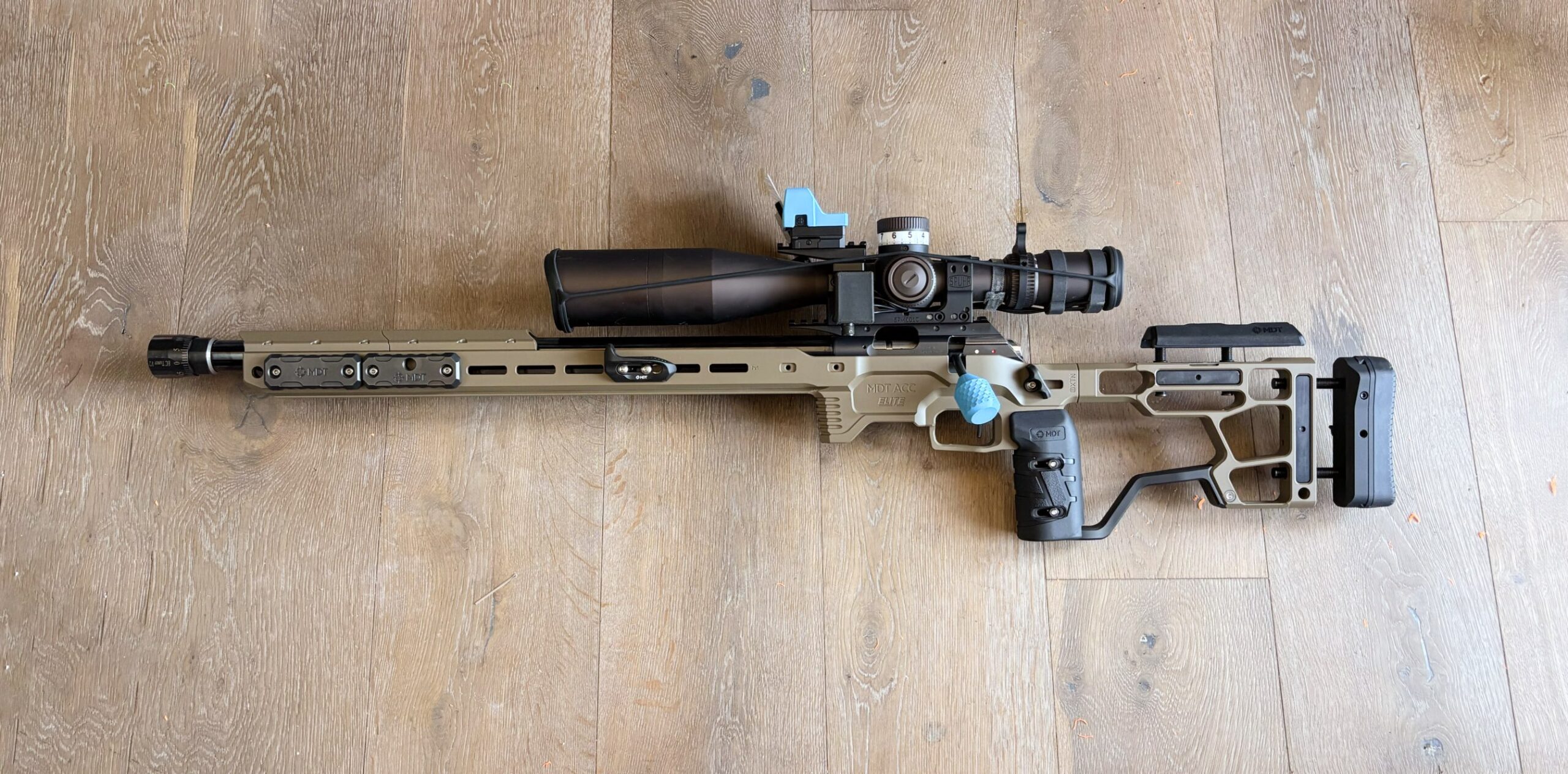
Being a left-handed PRS shooter often means accepting that the chassis you want is not available for your action and orientation. I had already been running my CZ 457 in a first-generation MDT ACC Premier, which I had converted by a gunsmith. When MDT released the ACC Elite for the CZ 457, I knew I wanted one—but, as always, the LH version was not available.
My gunsmith could do the work, but not for another month. That was far too long to stare at a brand-new chassis without using it, so I developed a process that could be completed with basic workshop tools and a few 3D-printed jigs. I will not pretend that drilling into a chassis worth roughly €1,700 was relaxing. It was daunting. Once I got past that first irreversible step, however, it got easier and the process worked. I am very happy with the result.
Important disclaimer: This article documents what I did to my own equipment. It is not professional gunsmithing advice or an MDT-approved procedure. Modifying the chassis will void its warranty, and a mistake could damage the chassis or affect the safe operation of the rifle. Work only on a completely unloaded rifle with all ammunition removed from the work area. Check the laws and competition rules that apply where you live, and consult a qualified gunsmith if you are not completely confident in the work.
A short review of the MDT ACC Elite for the CZ 457
In my opinion, the ACC Elite is the best competition chassis currently on the market. Most of the features that make the Remington 700 version so good have carried over to the CZ 457 model: the long, full-length ARCA forend; internal and external weight-tuning options; a rigid grip-to-buttstock connector bar; adjustable thumb rests; mounting points everywhere; and the highly adjustable SRS-X Elite buttstock.
MDT describes the platform as having a tunable weight system and fully adjustable ergonomics. The cheek rest, length of pull and buttpad height can all be adjusted without tools, while two hex keys are stored magnetically beneath the cheekpiece. The chassis is machined from 6061 aluminium, hard-anodized and Cerakoted. MDT lists the complete chassis at 6.10 lb (2.77 kg), with a length of pull from 12.25 to 14.75 inches. Those specifications make it clear that this is a serious, highly configurable competition platform rather than a lightweight field stock.
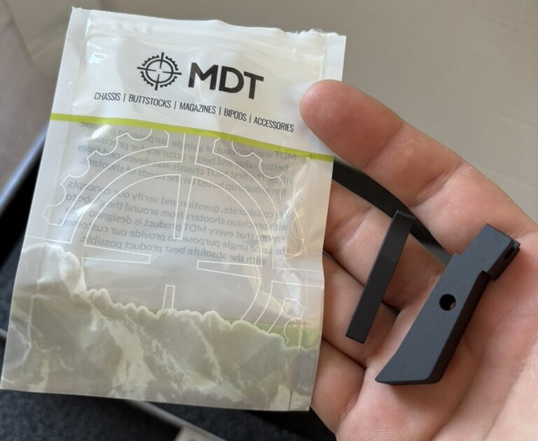
The CZ 457 version differs from the centre-fire ACC Elite. The CZ does not use an AICS magazine; its factory rimfire magazine interfaces with a separate magazine housing attached to the action. As a result, the CZ version does not come with the Elite’s adjustable AICS magazine latch.
Instead, MDT supplies an aluminium ejector block and an extended magazine release. I have not tested these parts because I use our own Position7 aluminium magwell kit, but the MDT parts look well made. In my view, the remaining weak point is still the factory plastic magwell. Adding rigid aluminium parts, especially a longer mag. release lever that can apply more leverage does not make the plastic component any stronger and may shorten its service life.
The smartest CZ-specific detail surprised me: MDT includes shorter barrel-retaining set screws. On a standard CZ 457, the original screws can protrude slightly below the action. A chassis then needs clearance around the front action screw, precisely where there is already very little material. The shorter screws let MDT retain more aluminium in that area and provide support where the action needs it. It is a small, thoughtful improvement over the first-generation ACC Premier. Kudos to MDT for this simple and effective solution.
My main criticism is the weight of the buttstock. Even after removing the supplied buttpad spacer, the balance point of my rifle moved rearward compared with my first-generation ACC Premier. The Elite gives you many ways to tune balance, but on a rimfire build the heavy rear section may require additional weight farther forward.
Overall, the chassis is exceptionally rigid, adjustable and competition-focused. For me, the CZ-specific compromises do not outweigh the strengths of the Elite platform—but they are worth understanding before buying one.
What this conversion does and does not do
This is only a half conversion. I use a right-handed Timney trigger with the safety removed because I do not use the safety in PRS competition. That makes the job much simpler: I only needed to create clearance for the left-handed bolt handle. I did not need to machine a separate pocket for a left-side safety lever.
If you need a functional safety—or if the law, your range or your competition rules require one—this guide is not suitable for your build. Have the work assessed and completed by a qualified gunsmith.
The conversion has two essential parts:
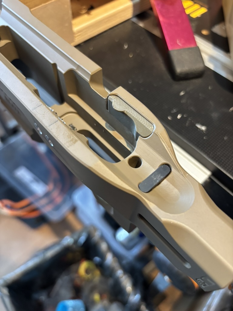
- Fill the existing right-hand safety opening. On a left-handed action, that opening sits beneath the bolt-stop pin. If it remains open, the pin can eventually work its way out. The bolt stop, pin and tiny spring can then disappear at exactly the wrong moment. Ask me how I know.
- Create a clearance slot for the left-hand bolt handle. The slot does not guide or lock the bolt; the action performs those functions. It only provides clearance for the handle to close, so a small amount of additional space is not critical.
Tools and materials
- 3D-printed chassis plug
- 3D-printed drilling jig
- 3D-printed cutting and filing guide
- 3D-printed sanding bar matching the slot profile
- 4.5 mm drill bit and a suitable hand drill
- Cutting lubricant
- Masking tape and clamps
- Flat pull saw
- Hand scroll saw
- Hand files; a miniature electric file is optional
- Coarse-to-fine abrasive paper (I used 240 and 500 grit)
- Small round and flat diamond files
- Cyanoacrylate (superglue) for retaining the plug
- Eye protection and a way to contain aluminium chips
Downloads: Download the plug, jigs and sanding-bar files here.
Step 1: Model the chassis and install the safety-opening plug
I measured the relevant part of the chassis and recreated it in Fusion 360. The first printed part was a plug for the right-hand safety opening. Filling this opening is not cosmetic: it prevents the left-hand action’s bolt-stop pin from escaping into the unused cutout.
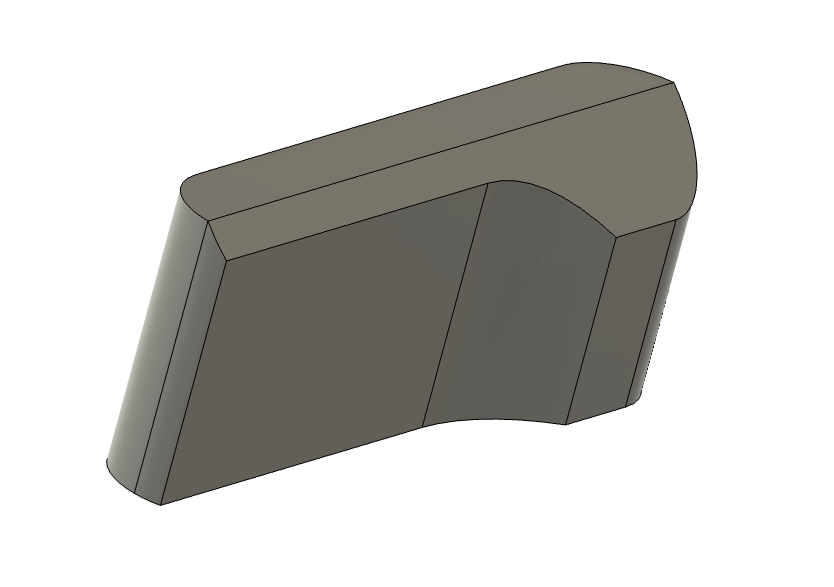
I retained the plug with a small amount of superglue. Once the action is installed, the plug is mechanically trapped and has nowhere to go; the glue simply keeps it from being lost when the rifle is disassembled.
Step 2: Print the drilling and cutting guides
I wanted the new left-side bolt-handle slot to copy the shape of the factory slot on the opposite side, including its rounded corners. The simplest way to reproduce those radii was to drill the corners first and then cut between the holes.
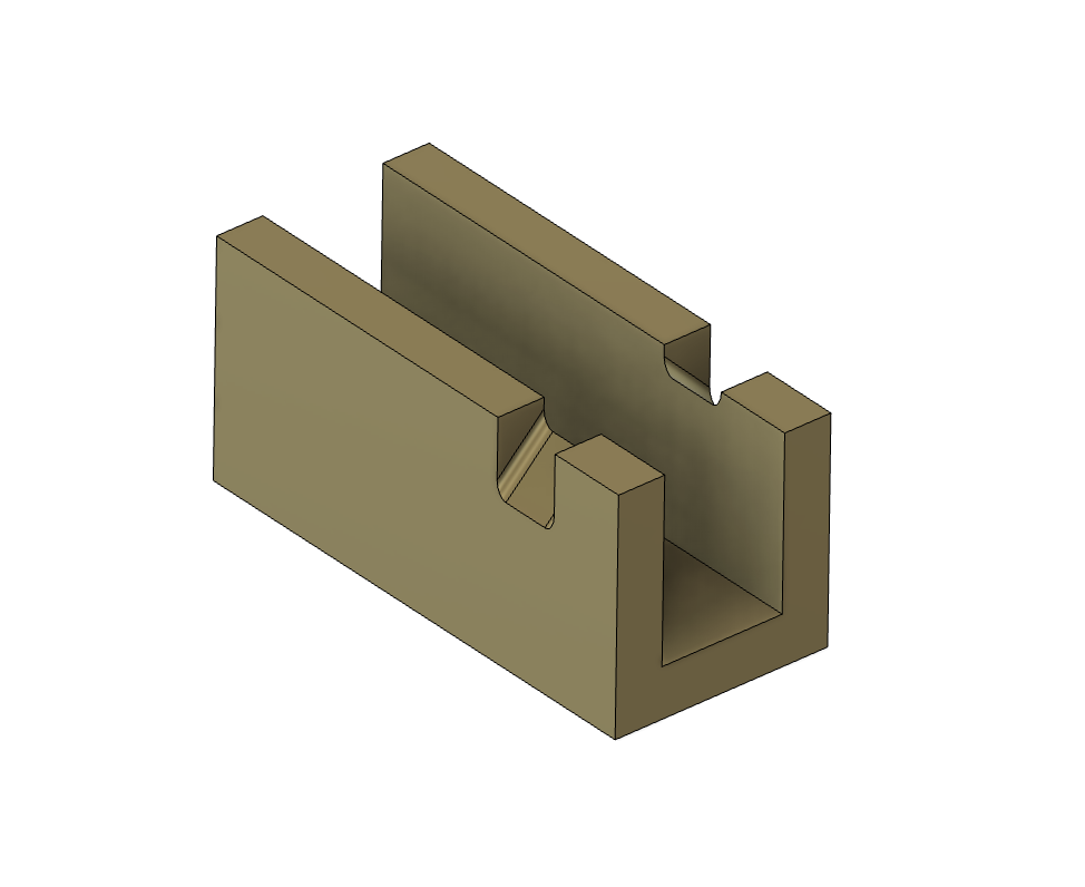
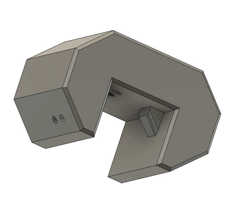
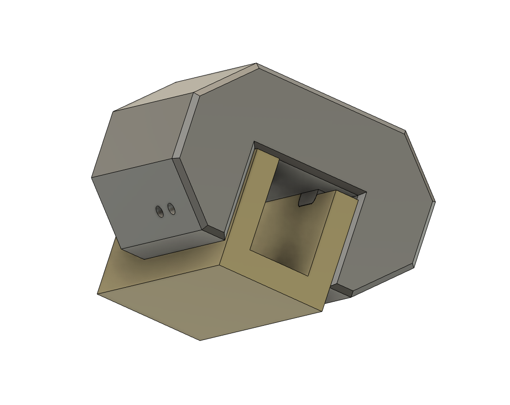
The first jig guides a 4.5 mm drill bit through two holes at 45 degrees. An internal locating feature fits into the original bolt slot on the opposite side of the chassis, transferring its position to the new side. The second jig guides the vertical saw cuts and later acts as a reference surface for filing and sanding.
Step 3: Drill the rounded corners
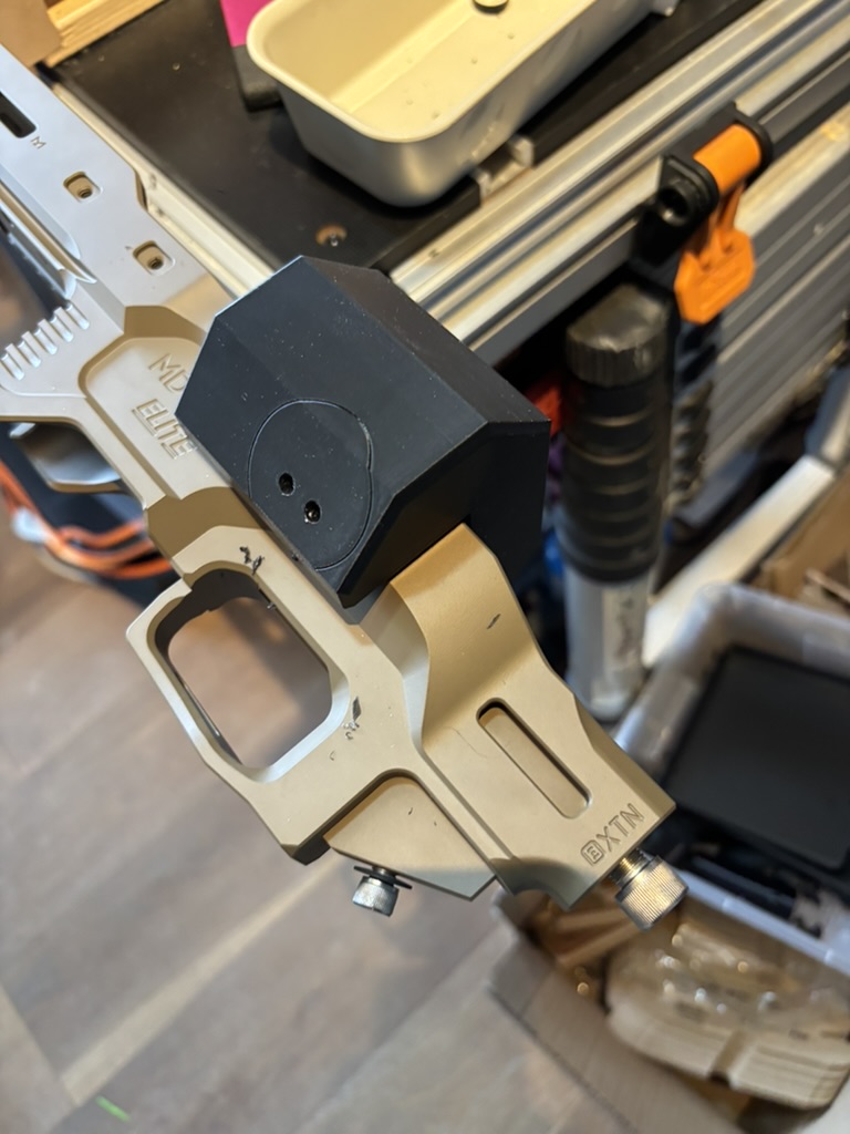
This was the most intimidating part because there was no easy way back. I fixed the jig in place with masking tape and two clamps, then checked that it was fully seated and could not move.
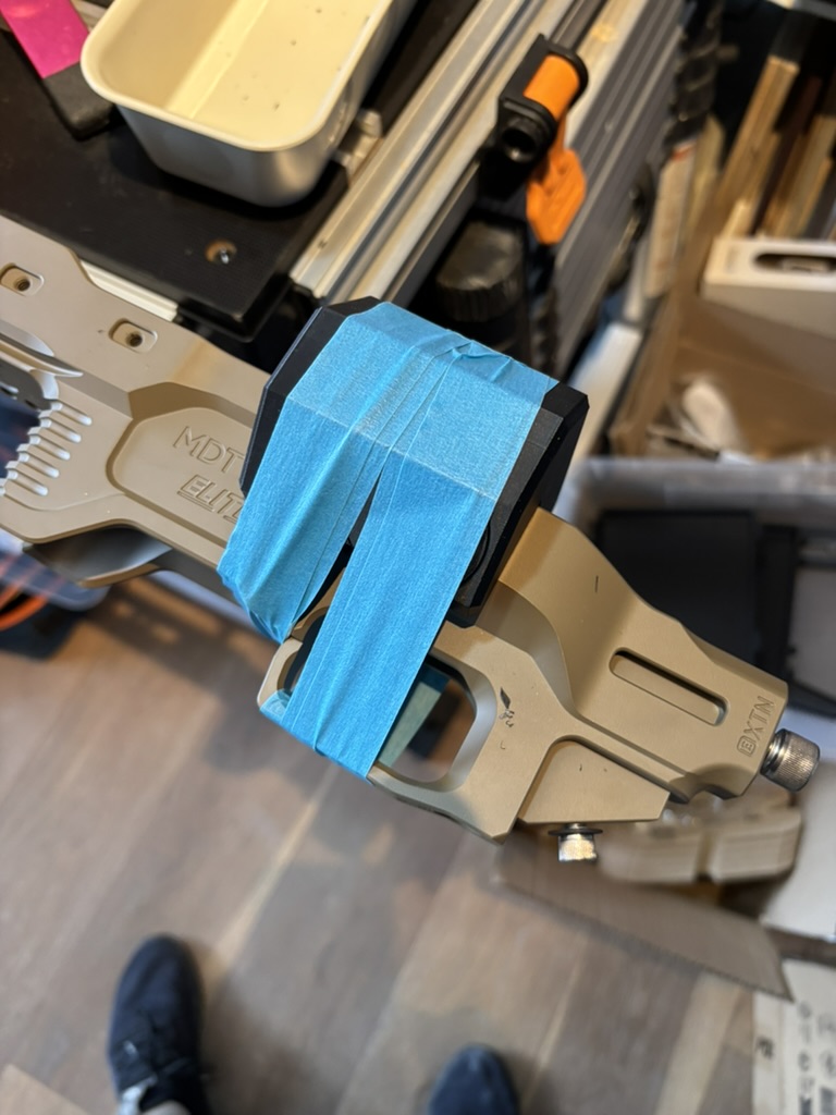
I applied cutting lubricant to both the bit and the guide hole, then drilled very slowly. Because the bit enters the chassis wall at 45 degrees, it will try to wander or grab if rushed. I withdrew it frequently to clear chips and reapply lubricant. After completing both holes, I removed the jig and inspected the result.
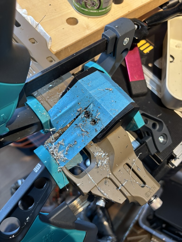
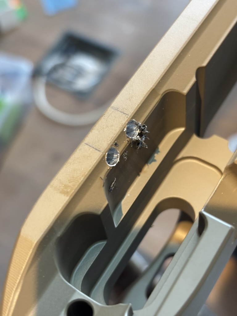
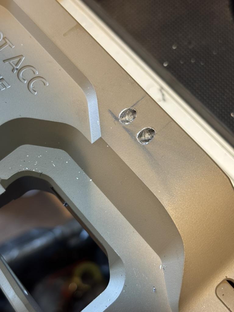
Drill slowly through the guide. Lubricate and clear chips frequently. The two 4.5 mm holes establish the rounded corners of the new slot.
Step 4: Cut the two side walls
Aluminium can be cut effectively with sharp woodworking tools. I installed the second guide and used a thin, flat pull saw to make the two straight side-wall cuts. The guide keeps the saw square to the slot while maintaining the required 45-degree angle.
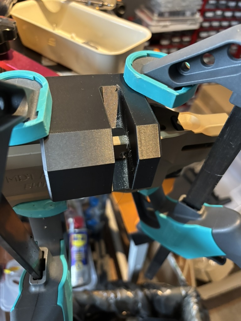
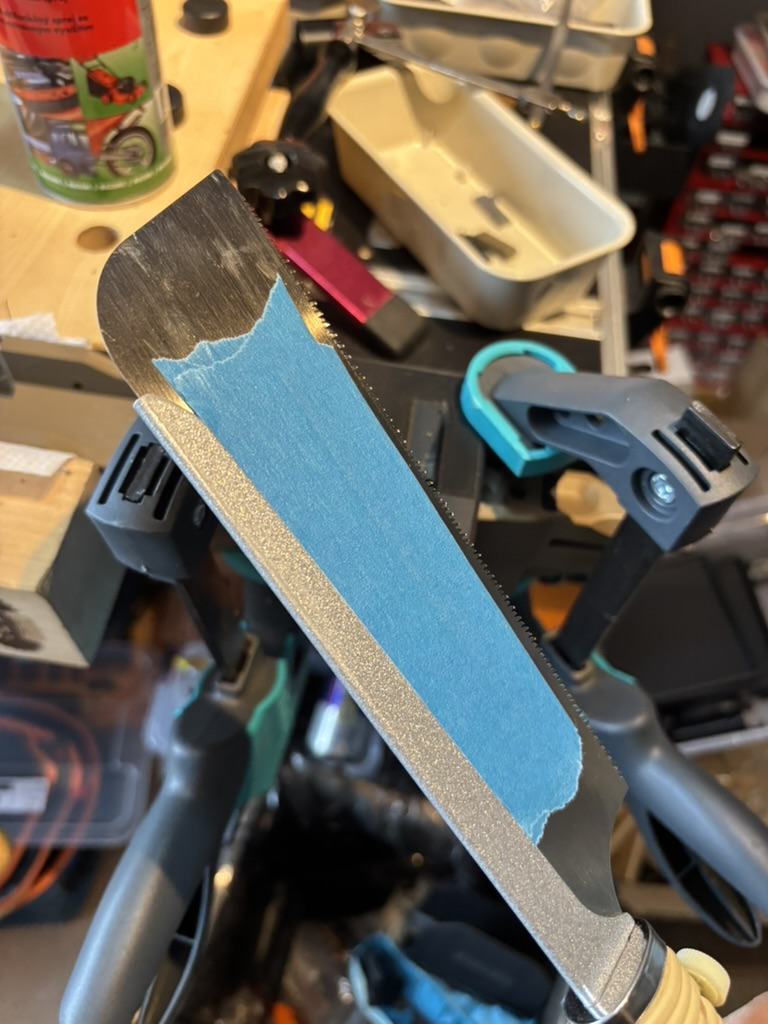
I initially added several layers of tape to the side of the saw because I was worried about making the slot too wide. In hindsight, that was unnecessarily cautious and created more filing later. If I repeated the job, I would use the saw without the extra tape and cut closer to the guide.
The flat pull saw I used for the two vertical cuts.
Step 5: Remove the centre section
I passed the blade of a hand scroll saw through one of the cuts, reassembled the saw and removed the bulk of the aluminium between them. The printed guide again provided the 45-degree reference. Cutting close to the guide at this stage saves a great deal of filing later, but I still left a small margin for final shaping.
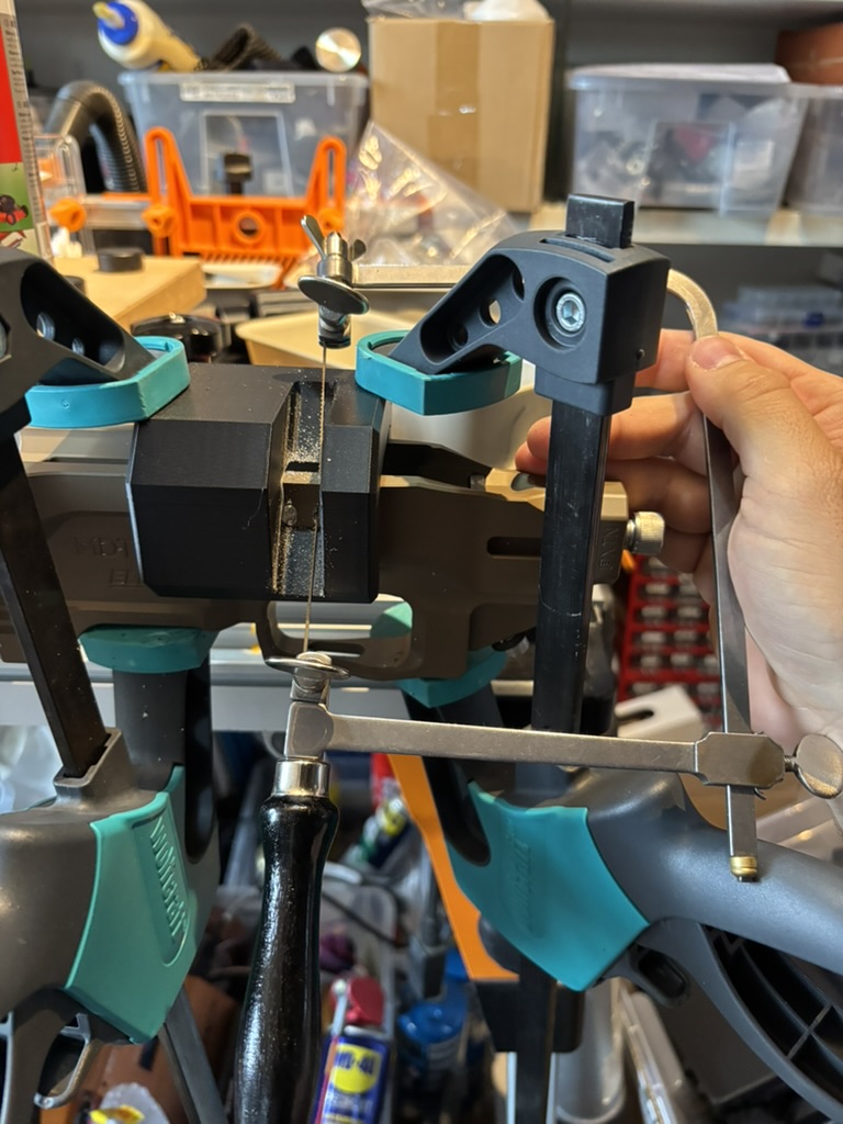
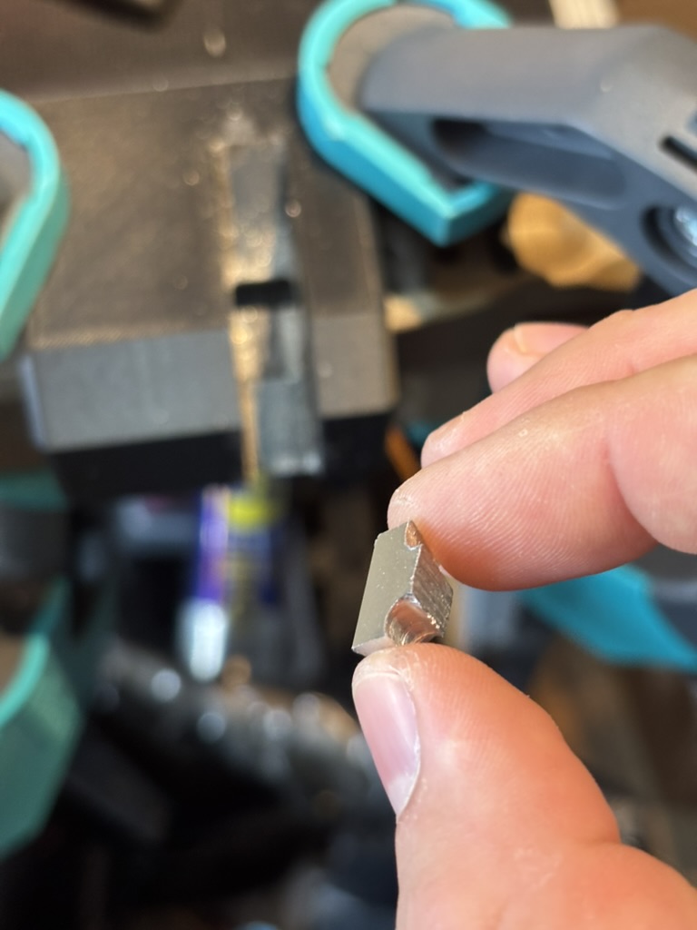
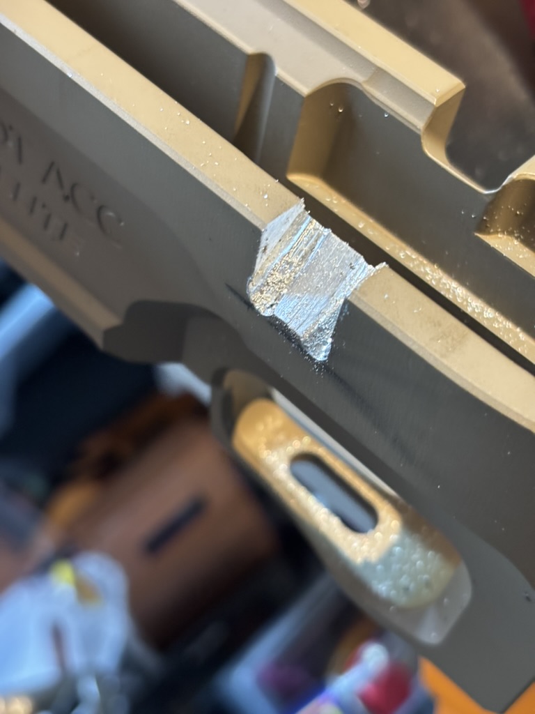
The rough opening after the saw work—functional in shape, but not yet finished. It looks like a mess but we will refine it now.
Step 6: File to the guide
Because I had cut conservatively, I spent about 30 minutes removing the remaining material with a hand file and a miniature electric belt file. I kept the files against the printed guide so that the walls remained straight and the 45-degree geometry stayed consistent.
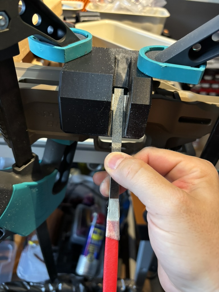
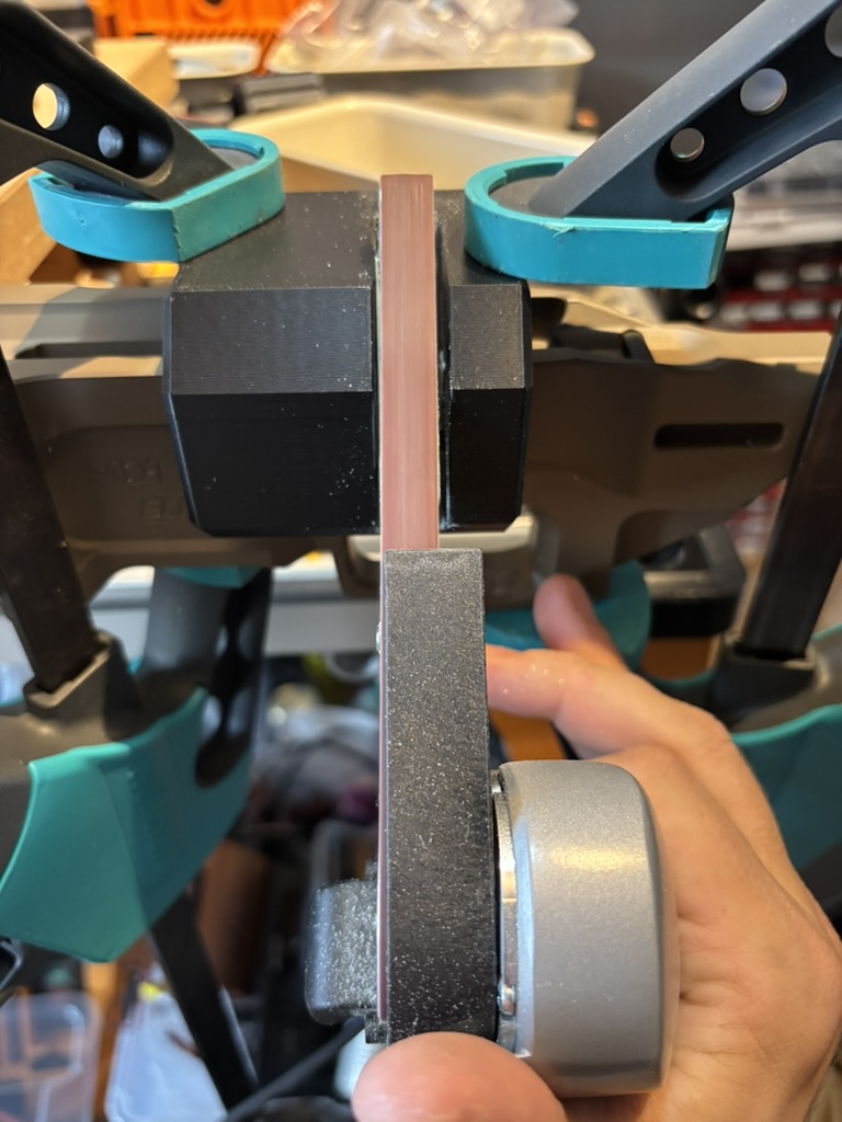
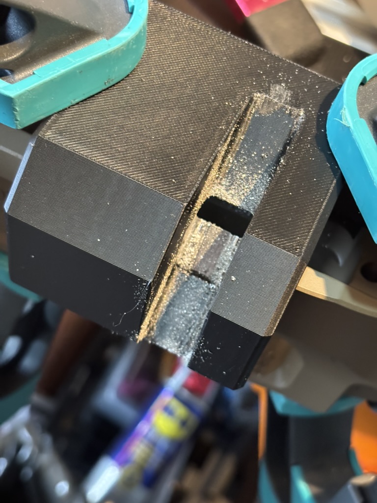
The miniature electric file sped up the rough shaping, but it is optional. Then Refining the shape with a hand file. Switch between the sides and the bottom surface. Do not touch the rounded corners, these will be refined in the next step.
Step 7: Sand the slot to its final profile
For the finishing stage, I printed a bar with the same profile as the intended slot. I cut strips of abrasive paper, wrapped them around the bar and used the guide to keep each stroke square.
I started with 240-grit paper. Looking back, I should have started coarser; aluminium clogged the paper quickly, and I used roughly two sheets—about 14 narrow strips—over another 30 minutes. Replacing clogged strips frequently was much faster than trying to keep using them.
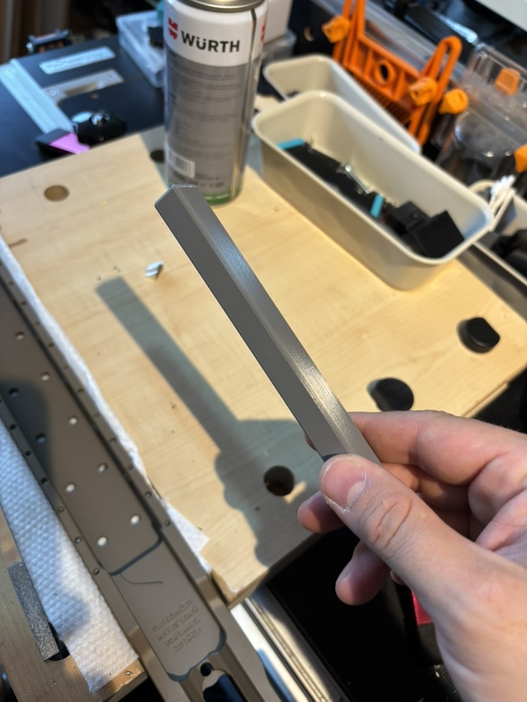
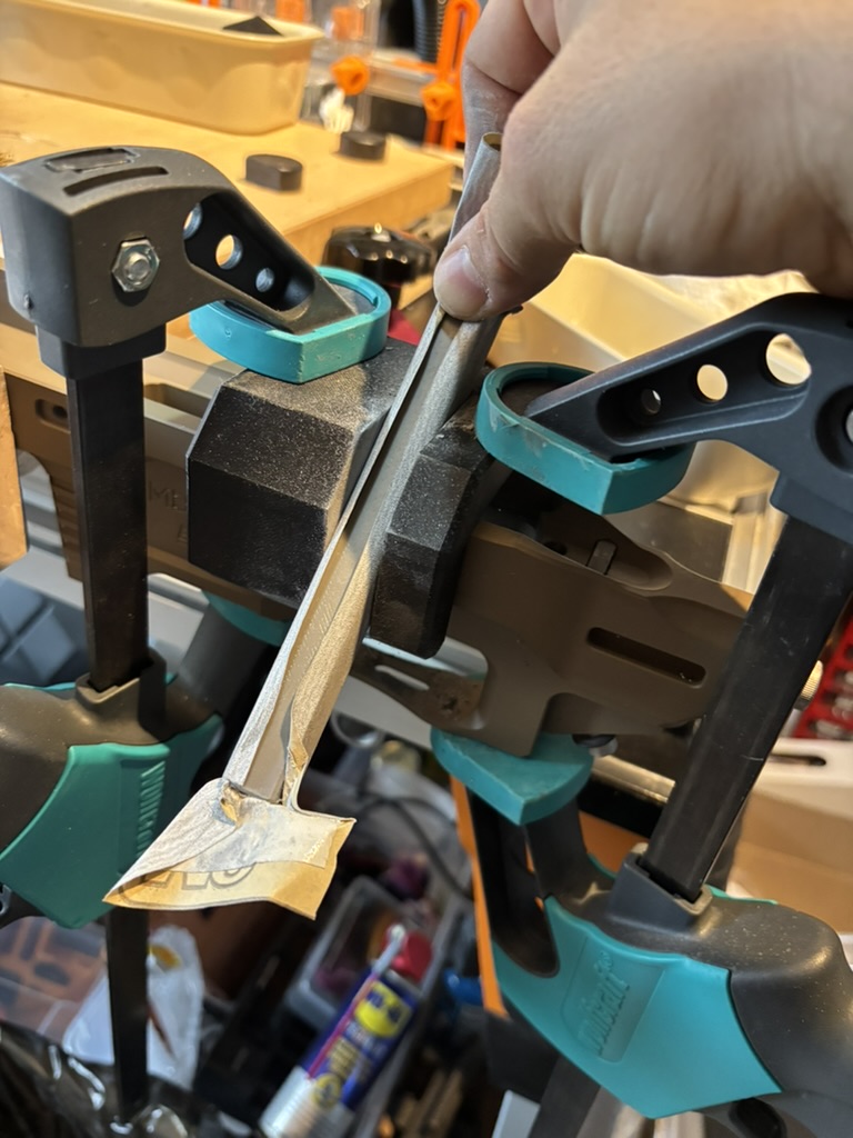
The profile bar and guide keep the finished surface flat and consistent.
Step 8: Finish the edges and check the fit
I continued sanding until the saw and file marks had disappeared, then completed two more passes with 500-grit paper. After removing the guide, I used small round and flat diamond files to add a very light chamfer to every sharp edge.
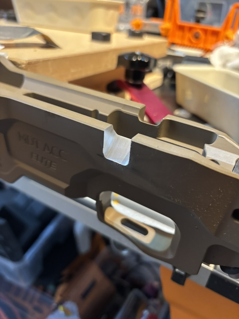
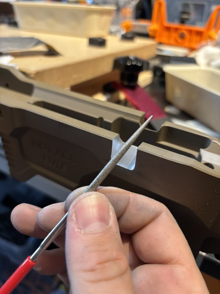
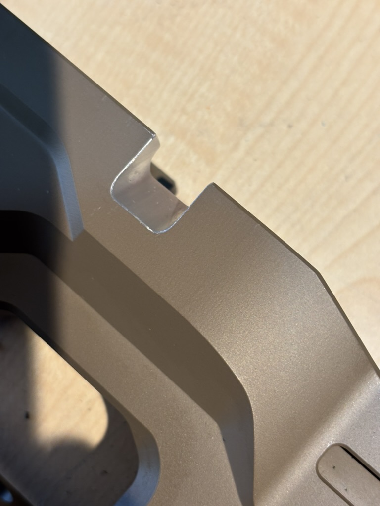
A very light chamfer removes the sharp edges. The completed slot before refinishing the exposed aluminium.
After cleaning every trace of aluminium swarf from the chassis and work area, I installed the action and checked that the bolt cycled and closed without touching the chassis. I stopped at bare aluminium, but the obvious final step is to degrease and refinish the cut surface with a suitable coating.
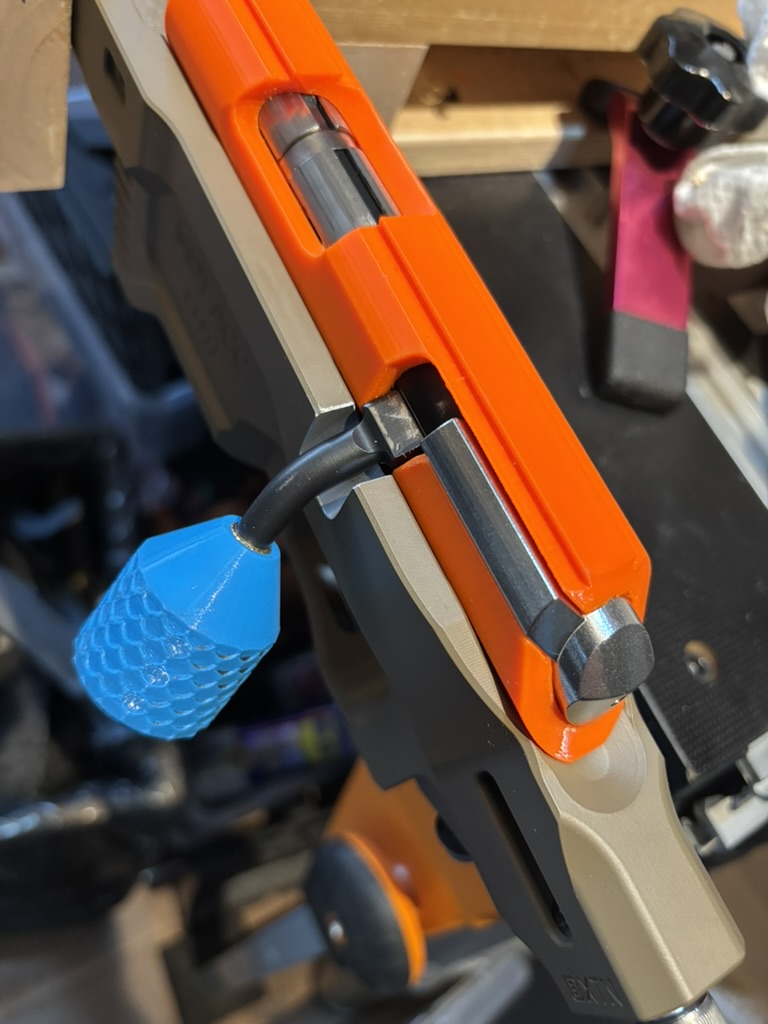
The result
I am genuinely pleased with how the conversion turned out. The cut is cleaner than the conversion on my first-generation ACC Premier, which was completed by a gunsmith. Because this build does not require a safety pocket, I removed only the material needed for bolt-handle clearance, preserving as much chassis stiffness as possible.
The key to making the job approachable was not a milling machine; it was taking the time to model the chassis and produce guides that controlled the location, angle and final shape at every stage. The operation still demands patience and confidence, but the jigs turn a freehand cut into a repeatable process.
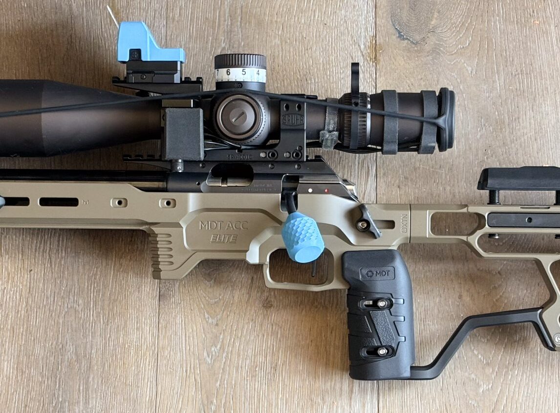
Ready for the range: the converted MDT ACC Elite with the left-handed CZ 457 action installed.
We hav made the 3D-print files for the plug, drilling jig, cutting guide and sanding bar available free of charge for anyone who wants to attempt the same conversion. Use them at your own risk, measure your own chassis and action, and stop if anything does not fit exactly as expected.
Sources and product information
- MDT ACC Elite Chassis System: official product page and specifications
- MDT overview of ACC Elite competition features
MDT, ACC Elite, CZ and Timney are trademarks of their respective owners. Position7 is not affiliated with or endorsed by those manufacturers unless expressly stated.